Wattstopper Power Pack Wiring Diagram
When using more sensors than this multiple power packs are required.
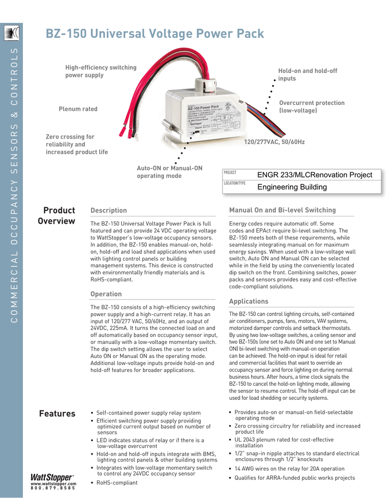
Wattstopper power pack wiring diagram. The bz 50 power pack is attached to existing junction boxes or mounted into fixture wiring trays. Always check local building codes. The bz 150 supplies low voltage power to occupancy sensors and other control devices switching line voltage in response to signals from control devices. The power pack is attached to existing junction boxes or mounted into fixture wiring trays.
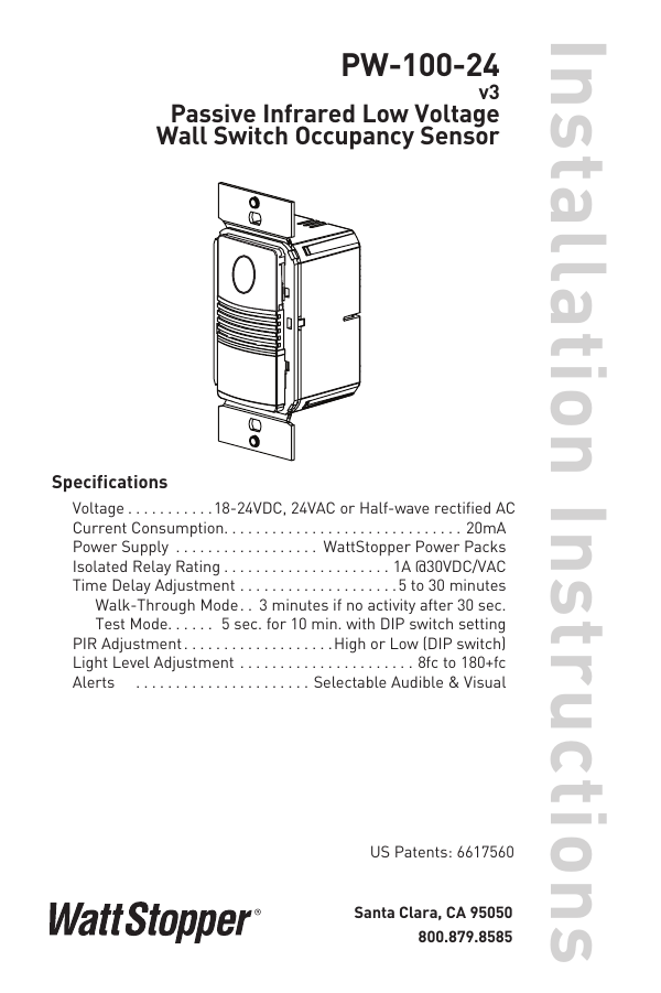
High voltage connections should use at least 14 gauge. For the bz 50 low voltage wiring should use at least 22 gauge wire. The power pack is attached to existing junction boxes or mounted into fixture wiring trays. Wiring directions each wattstopper bz series power pack can supply power for 7 dt 305 sensors.
Refer to the wiring diagram on the next page for the following procedures. Description the bz 150 power packs is the foundation for any low voltage lighting control system. Before installing the power pack. 2 power packs are designed to attach to existing or new electrical enclosures with 5 125 40mmj knockout check electrical codes in your area.
The power pack is attached to existing junction boxes or mounted into fixture wiring trays. 3 most applications require ul listed 18 22 awg 3 conductor class 2 cables for low voltage wiring. After initial wiring is complete check wiring diagram to verify power pack is wired correctly. Low voltage wiring should use at least 22 gauge wire.
Local and national electrical codes and requirements. 2 power packs are designed to attach to existing or new electrical enclosures with 5 125 40mmj knockout check electrical codes in your area. High voltage connections should use at least 14 gauge. Visit our website for faqs.
After initial wiring is complete check wiring diagram to verify power pack is wired correctly. 1 all wattstopper power packs should be installed in accordance with state. Always check local building codes. Connect the low voltage.
High voltage connections should use at least 14 gauge. Low voltage wiring should use at least 22 gauge wire high voltage connections should use at least 14 gauge. Red wire 24vdc from power pack to the 24v terminal on the sensor. 12 18 awg cu only strip gage 1 2 12 7mm.
The power pack is attached to existing junction boxes or mounted into fixture wiring trays. After initial wiring is complete check wiring diagram to verify power pack is wired correctly.


