Voltage Controlled Resistor Cadence

Cadence Use Voltage As A Parameter To Change Resistance Electrical Engineering Stack Exchange
Voltage Controlled Resistor
Vcvs Impedance Dips In Frequency Custom Ic Design Cadence Technology Forums Cadence Community
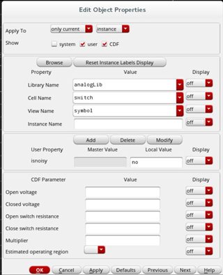
How To Control Isnoisy Property For Analoglib S Switch Component Custom Ic Design Cadence Technology Forums Cadence Community

Veriloga Models In Cadence Custom Ic Design Cadence Technology Forums Cadence Community
Convergence Problems Using Analoglib Switch Dc Simulation Custom Ic Design Cadence Technology Forums Cadence Community
I then input 100k as the volt res conversion factor and voi la.
Voltage controlled resistor cadence. In this case we have a 5 ohm resistor. I v curves for a resistor and diode illustrating their linear and nonlinear resistance respectively. The anl misc lib library file contains subcircuit models for voltage controlled reactances and admittances. Two types of fets are often used.
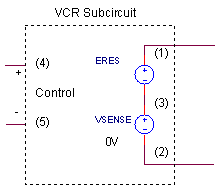
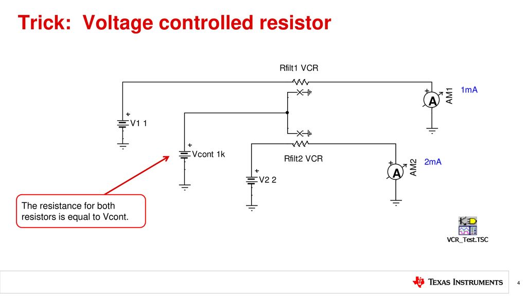
A simple addition to the above resistor model gives you a voltage controlled resistor. The jfet and the mosfet there are both floating voltage controlled resistors and grounded floating. Here s a subcircuit for this device subckt vc res1 10k 1 2 4 5 eres 1 3 value i vsense 10k v 4 5 vsense 3 2 dc 0v ends. C4 1pf m 0 5 vj 1 0 ecopy 3 6 1 2 1 0 vsense 0 6 0v.
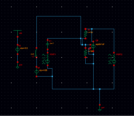
Since the load is in series with the resistor r the output current is always proportional to the input voltage regardless of the load resistance within limits of course e g you won t be able to drive 10 ma through a 1 mω load unless you can find amplifiers that accept supply voltages up to 10 000 v or so. A voltage controlled resistor vcr is a three terminal active device with one input port and two output ports. Conventionally implementation in circuit simulators of resistor models that can support zero or small valued resistances is done by changing the model formulation from i v r which is preferred for nodal analysis but cannot be used for r 0 to v ir for small values of resistance or by collapsing the nodes between which the resistor is connected for r 0. I solved the problem by using a voltage controlled resistor vcres from the analoglib on cadence and tying the positive node to vh and the negative terminal to vl.
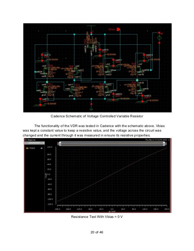
V i x r x vc. All you need is a controlling voltage to multiply the resistor value. The input port voltage controls the value of the resistor between the output ports. From this curve we can easily extract the resistance of the resistor from the slope of the line.
This can be modelled using a voltage controlled current source with voltage controlled by table based voltage controlled current source. The image below shows i v curves for a resistor and a diode driven with a dc voltage source. These can be used to make voltage controlled resistors and capacitors.

Awr Microwave Office Element Catalog Voltage Controlled Voltage Source Vcvs2

Question Regarding Voltage Controlled Resistors In Pspice Electrical Engineering Stack Exchange
Created By Tim Green Art Kay Presented By Peggy Liska Ppt Download
Https Inst Eecs Berkeley Edu Ee105 Fa17 Labs Lab0 Pdf
Controlled Impedance Elements A Single Ended Voltage Variable Download Scientific Diagram

Pseudo Resistors A Voltage Controlled Transistor B Complementry Download Scientific Diagram
Https Www Sciencepubco Com Index Php Ijet Article Download 16553 7068

Ev 5519 Simulating An Rc Circuit In Ltspice With An Initial Condition Free Diagram
Implementing Analog Multiplexers In Ltspice And Cadence Virtuoso Electrical Engineering Stack Exchange

In Cadence Orcad Pspice Objective Of Lecture Introduce The Parts In Pspice For Dependent Voltage And Current Sources Describe How To Set The Part Properties Ppt Download

A Voltage Tunable Cmos Differential Active Resistor And Its Application Maundy 2019 International Journal Of Circuit Theory And Applications Wiley Online Library
First Order Voltage Controlled Filters A Lowpass Fixed Dc Gain Pole Download Scientific Diagram
Integrated Mixed Signal Guitar Effects Chip

