Vav Box Control Sequence
Coordinate with electrical lighting design for dual use.
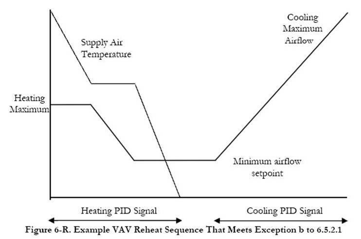
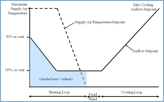
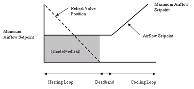
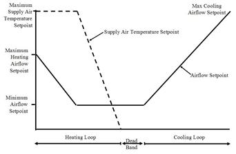
Vav box control sequence. Vav boxes with hot water reheat. Johnson controls ddc for bacnet or n2 etc. Conventional vav box logic. Vav boxes with reheat coils were traditionally controlled using the con trol logic shown in.
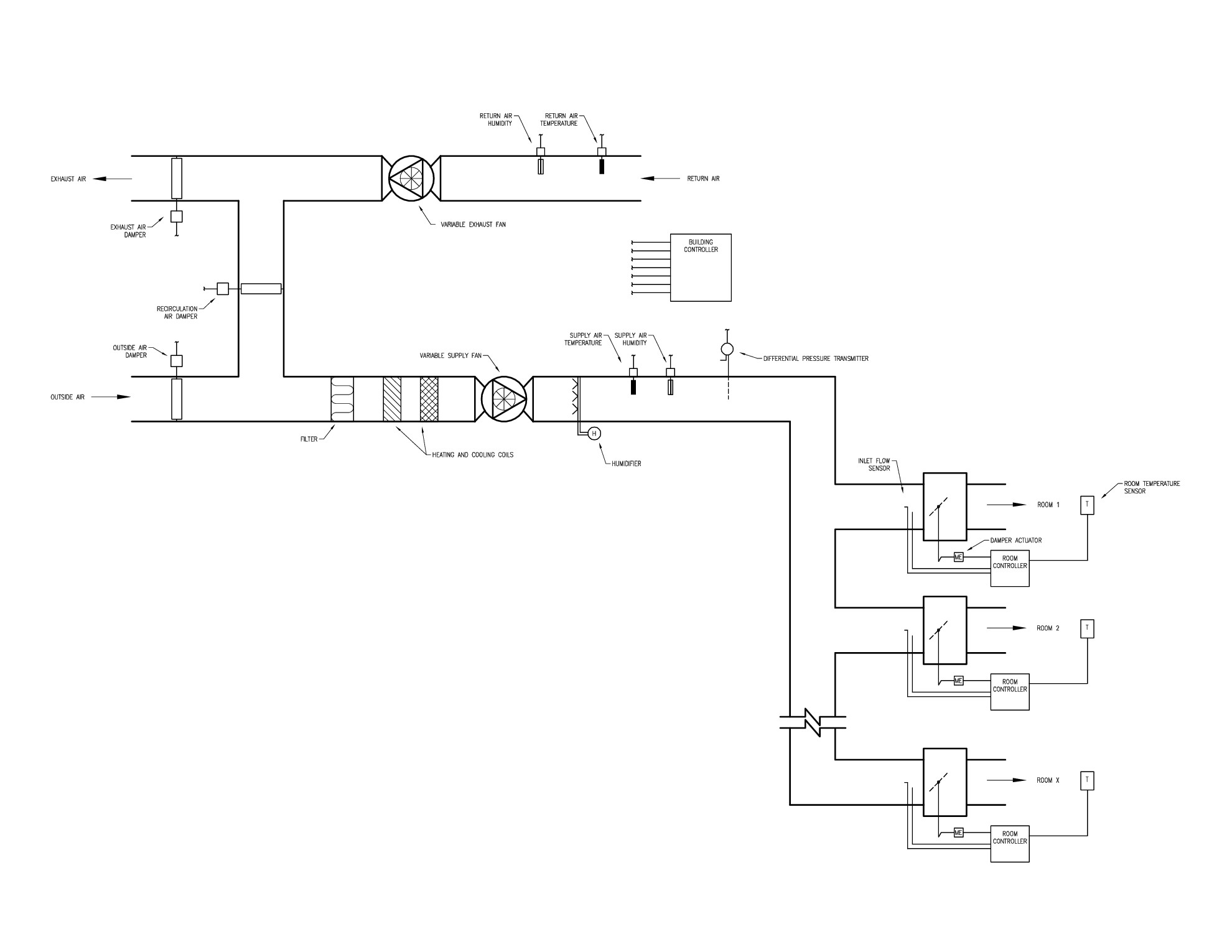
Patented flowstartm airflow sensor standard electric control box. A dual duct box has inlets control dampers. Reference standard control diagrams ic 16. Vav box control sequences ahu control sequences zone groups dp setpoint reset sat setpoint reset outdoor air control minimum outdoor air control demand controlled ventilation automatic fault detection and diagnostics alarms.
Typical sequence of operation for a vav box non fan powered heating and cooling mode heating mode sequence of operation non fan powered on call for heat from the thermostat a signal is sent to the ddc controller. Jfactory mounted consignment ddc standard control features. Provide the following for all air terminal unit boxes. It is a commercially manufactured box with a control damper inlet and outlet connections and options such as flow pickups return air plenum inlet heating coil and fan.
So in the sequence of operation for a fan powered vav box and a non fan powered vav box would include closing the damper to allow minimal air from the air handler and at the same time energize the fan contactor so that the fan in the vav box comes on and pulls warmer air from the plenum. Vav terminal unit commonly called a vav box this mechanical equipment modulates airflow to the space with the johnson controls vav controller. The sup ply airflow setpoint is reset from the zone maximum airflow setpoint when the space is at full cooling proportion ally down the zone minimum when no cooling is required. From the most basic to the most sophisticated sequence of operation the controls are designed by experts in vav single duct terminal operation.
The intent is for this sequence to be included in the contract drawings.

