Vav Box Control Logic

Interpreting Piping And Instrumentation Diagrams Symbology Chenected Piping And Instrumentation Diagram Process Control Chemical Engineering

Original Control Logic And Operation Schedule For Vav Box Download Scientific Diagram

Fieldserver Application For Integration Into An Emerson Deltav Of Hvac Units A Genset Vav Boxes Fire Alarm And Chillers Hvac Unit Fire Alarm Vav

Pin On To Study

Interpreting Piping And Instrumentation Diagrams Symbology Chenected Piping And Instrumentation Diagram Process Control Chemical Engineering

Wiring Diagram Home Wiring Diagram Home Wiring Diagram For Smart Home 3 12rma Lift Hvac Design Hvac System Hvac

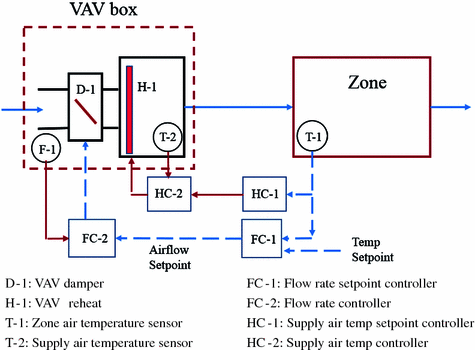
This airflow setpoint is used by.
Vav box control logic. 6 vav terminal control applications application note pressure independent an improved vav box control strategy employs cascaded proportional integral control loops. Summarizes a detailed analysis of vav box control and selection1 and provides vav boxes sizing criteria that will mini mize lcc in typical applications. Conventional vav box logic. Vav boxes with reheat coils were traditionally controlled using the con trol logic shown in.
A vav box is integral to the ductwork connecting primary ductwork to secondary ductwork. The sup ply airflow setpoint is reset from the zone maximum airflow setpoint when the space is at full cooling proportion ally down the zone minimum when no cooling is required. Vav controls and airflow setpoints figure 1 shows a single duct vav box using pressure independent control logic. A variable air volume vav box is a part of an hvac system in commercial buildings.
Vav box control logic. Dual maximum vav box logic summary title 24 requires dual maximum logic for vav zones with ddc setpoints set minimum and heating maximum setpoints as low as possible minimum allowed by controls is seldom a factor if box properly sized do not use maximum allowed by t 24 just because it is legal cost impact. If the fan airflow is higher than the pre set critical value 70 of the design flow the fan speed is proportionally adjusted based on the airflow ratio. In many cases a variable air volume box is nothing but an assembly of a sheet metal box with a damper and controls inside a control panel.

New Electrical Symbols For Outlet Diagram Wiringdiagram Diagramming Diagramm Visuals Visualisation Graphi Diagram Electrical Symbols Single Line Diagram

Hvac Compressor Troubleshooting Hvac Wiring Schematic Exercises Hvac Technician Day In The Life Johnstone Hvac Parts Hvac Hvac Duct Electrical Diagram

Hvac Plan Floor Plan Solutions Floor Plan Symbols Floor Plans Hvac

Schematic Diagram Of A Pressure Independent Vav Box With Hydronic Download Scientific Diagram

Honeywell Thermostat Wiring Instructions Diy House Help Thermostat Wiring Honeywell Thermostats Thermostat Installation

Gd T Symbols Reference Guide From Sigmetrix Engineering Symbols Mechanical Design Engineering Design
Modeling And Control Strategies For Vav Systems Springerlink
Https Docs Johnsoncontrols Com Bas Reader Pnbjoq9randcl622qbnwaa Dzqsjwpowr60e1lyf41lg

Unitary Plc Advantages And Disadvantages Plc Programming Basic System

Pin By Basilio On Electricidad Industrial Electrical Symbols Electrical Layout Architecture Symbols

Vav Box Control Loop The Purpose Of The Vav Box Control Loop Is To Adjust Airflow Through The Box To Maintain A Space Temperature The Difference Between Ppt Video Online Download

Stay Grounded Funny Electrical Symbol Engineer Hoodie Shirts Cool T Shirts T Shirt

